texcoord (Pixel Shader)
Interprets texture coordinate data (UVW1) as color data (RGBA).
Syntax
texcoord (Pixel Shader) dest
Registers
- dest
- Destination register.
Remarks
Pixel shader versions 1_1 1_2 1_3 1_4 2_0 2_x 2_sw 3_0 3_sw texcoord x x x This instruction interprets the texture coordinate set (UVW1) corresponding to the destination register number as color data (RGBA). If the texture coordinate set contains fewer than three components, the missing components are set to 0. The fourth component is always set to 1. All values are clamped between 0 and 1.
The advantage of texcoord (Pixel Shader) is that it provides a way to pass vertex data interpolated at high precision directly into the pixel shader. However, when the data is written into the destination register, some precision will be lost, depending on the number of bits used by the hardware for registers.
No texture is sampled by this instruction. Only texture coordinates set on this texture stage are relevant.
Any texture data (such as position, normal, and light source direction) can be mapped by a vertex shader into a texture coordinate. This is done by associating a texture with a texture register using ID3DXBaseEffect::SetTexture and by specifying how the texture sampling is done using IDirect3DDevice9::SetTextureStageState. If the fixed function pipeline is used, be sure to supply the TSS_TEXCOORDINDEX flag.
This instruction is used as follows:
texcoord tnA texture register (tn) contains four color values (RGBA). The data can also be thought of as vector data (xyzw). texcoord (Pixel Shader) will retrieve three of these values (xyz) from texture coordinate set x, and the fourth component (w) is set to 1. The texture address is copied from the texture coordinate set n. The result is clamped between 0 and 1.
Examples
This example is for illustration only. The C code accompanying the shader has not been optimized for performance. It can use helper functions from the Sample Framework. The sample framework is the foundation on which many of the samples are built.
Here is an example shader using texcoord (Pixel Shader).
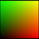
ps_1_1        ; version instruction
texcoord t0   ; declare t0 hold texture coordinates,
              ; which represent rgba values in this example
mov r0, t0    ; move the color in t0 to output register r0
The rendered output from the pixel shader is shown below. The (u,v,w,1) coordinate values map to the (rgb) channels. The alpha channel is set to 1. At the corners of the image, coordinate (0,0,0,1) is interpreted as black, (1,0,0,1) is red, (0,1,0,1) is green, and (1,1,0,1) contains green and red, producing yellow.
Additional code is required to use this shader and an example scenario is shown below.
// This code creates the shader from a file. The contents of
//   the shader file can also be supplied as a text string.
TCHAR               strPShaderPath[512];
LPD3DXBUFFER        pCode;
DXUtil_FindMediaFile( strPShaderPath, _T("shaderFile.txt") );

// Assemble the vertex shader from the file.
D3DXAssembleShaderFromFile( strPShaderPath, 0, NULL, &pCode, NULL );
m_pd3dDevice->CreatePixelShader((DWORD*)pCode->GetBufferPointer(),
                   &m_hPixelShader );
pCode->Release();

// This code defines the object vertex data.
struct CUSTOMVERTEX
{
    FLOAT x, y, z;
    FLOAT tu1, tv1;
};

#define D3DFVF_CUSTOMVERTEX (D3DFVF_XYZ|D3DFVF_TEX1|TEXCOORD2(0))

static CUSTOMVERTEX g_Vertices[]=
{
    //  x      y     z     u1    v1
    { -1.0f, -1.0f, 0.0f, 0.0f, 0.0f, },
    { +1.0f, -1.0f, 0.0f, 1.0f, 0.0f, },
    { +1.0f, +1.0f, 0.0f, 1.0f, 1.0f, },
    { -1.0f, +1.0f, 0.0f, 0.0f, 1.0f, },
};
Instruction Information
Minimum operating systems Windows 98