| Microsoft DirectX 9.0 |
The VMR can render multiple input streams. In this configuration, called mixing mode, the VMR loads its mixer and compositor to perform the mixing and blending prior to rendering. Mixing mode can be used either while the VMR is in windowed mode or windowless mode.
Mixing mode requires that the graphics driver supports the DDCAPS_BLTFOURCC and DDCAPS_BLTSTRETCH capability flags (color space conversion and stretch blitting, respectively). Almost all new graphics drivers have those capabilities. In addition, the driver must support the creation of Direct3D render targets for the current display pixel depth. Some devices do not support Direct3D operations when the display is set to 24 bits per pixel. For more information, see the DirectX Graphics SDK documentation.
Note When the VMR is mixing multiple video streams, the filter graph does not seek correctly. If you need to seek multiple video streams, you must create separate filter graphs that share the same custom allocator-presenter object. The VMRMulti sample application illustrates this approach.
Configuring the VMR-7 for Multiple Streams
To render multiple input streams with the VMR-7, do the following:
Configuring the VMR-9 for Multiple Streams
By default, the VMR-9 creates four input pins. If you want to mix more than four video streams, call IVMRFilterConfig9::SetNumberOfStreams before connecting any input pins. Use the IVMRMixerControl9 interface to set the stream parameters, such as alpha, Z-order, and position.
Positioning and Moving Video Rectangles in Composition Space
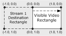
When the VMR mixes multiple input streams, it positions each stream within a normalized rectangle, called "composition space." Within composition space, the coordinates (0.0, 0.0) to (1.0, 1.0) form the visible video rectangle. Any coordinates that fall outside of this rectangle are clipped.
An application can perform special effects with moving, stretching, and shrinking the video from an input stream, by changing the destination rectangle in composition space for that stream. If the specified rectangle is a different size than the native video rectangle, the native video will be shrunk or stretched to fit. The destination rectangle is specified by calling the IVMRMixerControl::SetOutputRect method.
For example, assume that stream 0 (which corresponds to pin 0) contains the main video stream, and stream 1 (which corresponds to pin 1) contains a secondary video. Stream 1 can be positioned completely offscreen by specifying a normalized rectangle of { -1.0f, 0.0f, 0.0f, 1.0f }. Stream 1 can then be moved into the visible area by modifying the left and right sides of the rectangle on successive calls to SetOutputRect:
| Time | Rectangle |
| t + 0 | { -1.0f, 0.0f, 0.0f, 1.0f } |
| t + 1 | { -0.9f, 0.0f, 0.1f, 1.0f } |
| t + 2 | { -0.8f, 0.0f, 0.2f, 1.0f } |
| ... | ... |
| t + 10 | { 0.0f, 0.0f, 1.0f, 1.0f } |

At time t+10, the video from stream 1 is completely visible. In this example, the native size of stream 1 was maintained while it was moving. You could also stretch or shrink the rectangle to produce interesting effects. You can also flip the video vertically, by specifying a greater value for the top than the bottom, or mirror the video horizontally, by specifying a greater value for the left than the right.