Texturing
This example applies a texture map to the object.
The vertex data contains object position data as well as texture position or uv data. This causes changes to the vertex declaration structure. The vertex data is also shown below.
struct CUSTOMVERTEX_POS_TEX1
{
    float       x, y, z;		// object position data
    float       tu1, tv1;		// texture position data
};

CUSTOMVERTEX_POS_TEX1 g_Vertices[]=
{
    //  x      y     z      u1    v1
    { -0.75f, -0.5f, 0.0f, 0.0f, 0.0f },	//  lower right
    {  0.25f, -0.5f, 0.0f, 1.0f, 0.0f },	//  lower left
    {  0.25f,  0.5f, 0.0f, 1.0f, -1.0f },	//  upper left
    { -0.75f,  0.5f, 0.0f, 0.0f, -1.0f },	//  upper right
};

D3DUtil_CreateTexture( m_pd3dDevice, TEXT("earth.bmp"),
               &m_pTexture0, D3DFMT_R5G6B5 );
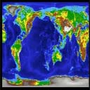
The texture image must be loaded. In this case, the file "earth.bmp" contains a 2-D texture map of the earth and will be used to color the object.
The vertex shader declaration needs to reflect the vertex position and texture coordinate data.
// Create the shader declaration.
D3DVERTEXELEMENT9 decl[] =
{
	{ 0, 0,  D3DDECLTYPE_FLOAT3, D3DDECLMETHOD_DEFAULT, D3DDECLUSAGE_POSITION, 0 },
	{ 0, 12, D3DDECLTYPE_FLOAT2, D3DDECLMETHOD_DEFAULT, D3DDECLUSAGE_TEXCOORD, 0 },
	D3DDECL_END()
};
This declaration declares one stream of data that contains the vertex position and the texture coordinate data.
The rendering code tells Microsoft?Direct3D?where to find the data stream and the shader, and sets up texture stages because a texture map is being applied.
m_pd3dDevice->SetStreamSource( 0, m_pQuadVB,
                               sizeof(CUSTOMVERTEX_POS_TEX1) );
m_pd3dDevice->SetVertexShader( m_pVertexShader );

m_pd3dDevice->SetTextureStageState( 0, D3DTSS_COLOROP,
                                               D3DTOP_MODULATE );
m_pd3dDevice->SetTextureStageState( 0, D3DTSS_COLORARG1,
                                               D3DTA_TEXTURE );
m_pd3dDevice->SetTextureStageState( 0, D3DTSS_COLORARG2,
                                               D3DTA_DIFFUSE );
m_pd3dDevice->SetTexture( 0, m_pTexture0 );
m_pd3dDevice->DrawPrimitive( D3DPT_TRIANGLEFAN, 0, 2 );
m_pd3dDevice->SetTexture( 0, NULL );
Because there is a single texture, the texture stage states need to be set for texture state 0. These methods tell Direct3D that the texel values will be used to provide diffuse color for the object vertices. In other words, a 2-D texture map will be applied like a decal.
Here is the shader.
vs_1_1               // version instruction
dcl_position v0      // declare position register
dcl_texcoord v8      // declare texture coordinate register
def c4, 1, 1, 1, 1   // initialize a constant
m4x4 oPos, v0, c0    // transform vertices by view/projection matrix
mov oD0, c4          // move diffuse color to output color register
mov oT0, v8          // move texture color to output texture register
The shader file contains several instructions that result in a texture-mapped object, which is shown below.