Texture Map with Lighting
This example uses a vertex shader to apply a texture map and add lighting to the scene. The object used is a sphere. The sample code applies a texture map of the earth to the sphere and applies diffuse lighting to simulate night and day.
The code sample adds to the Shader3 example by adding lighting to a texture mapped object. Refer to Shader3 for information about loading the texture map and setting up the texture stage states.
There is a detailed explanation of the sample code framework at Sample Framework. You can cut and paste the sample code into the sample framework to quickly get a working sample.
Vertex Shader Creation
The vertex data has been modified from the Shader3 sample to include vertex normals. For lighting to appear, the object must have vertex normals. The data structure for the vertex data is shown below.
struct CUSTOMVERTEX_POS_NORM_COLOR1_TEX1
{
    float       x, y, z;        // position
    float       nx, ny, nz;     // normal
    DWORD       color1;         // diffuse color
    float       tu1, tv1;       // texture coordinates
};
A shader declaration defines the input vertex registers and the data associated with them.
// Create the shader declaration.
D3DVERTEXELEMENT9 decl[] =
{
	{ 0, 0,  D3DDECLTYPE_FLOAT3,   D3DDECLMETHOD_DEFAULT, D3DDECLUSAGE_POSITION, 0 },
	{ 0, 12, D3DDECLTYPE_FLOAT3,   D3DDECLMETHOD_DEFAULT, D3DDECLUSAGE_NORMAL,   0 },
	{ 0, 24, D3DDECLTYPE_D3DCOLOR, D3DDECLMETHOD_DEFAULT, D3DDECLUSAGE_COLOR,  0 },
	{ 0, 28, D3DDECLTYPE_FLOAT2,   D3DDECLMETHOD_DEFAULT, D3DDECLUSAGE_TEXCOORD, 0 },
	D3DDECL_END()
};
This declares one stream of data, which contains the vertex position, normal, diffuse color, and texture coordinates.
Next, create the shader. You can create a shader from an ASCII text string or load it from a shader file that contains the same instructions. This example uses a shader file.
// v7  vertex diffuse color used for the light color
// v8  texture
// c4  view projection matrix
// c12 light direction

vs_1_1                       // version instruction
dcl_position v0              // declare register data
dcl_normal v4                // v0 is position, v4 is normal
dcl_color0 v7                // v7 is diffuse color
dcl_texcoord0 v8             // v8 is texture coordinates
m4x4 oPos, v0, c4            // transform vertices using view projection transform
dp3  r0, v4, c12             // perform lighting N dot L calculation in world
mul  oD0, r0.x , v7          // calculate final pixel color from light intensity and
                             // interpolated diffuse vertex color
mov  oT0.xy , v8             // copy texture coordinates to output
You always enter the version instruction first. The last instruction moves the texture data to the output register oT0. After you write the shader instructions, you can use them to create the shader.
LPDIRECT3DPIXELSHADER9 m_pVertexShader;
TCHAR        strShaderPath[512];
LPD3DXBUFFER pCode;                  // buffer with the assembled shader code
LPD3DXBUFFER pErrorMsgs;             // buffer with error messages
DXUtil_FindMediaFileCb( strShaderPath, sizeof(strShaderPath),
                        _T("VertexShader3.vsh") );

D3DXAssembleShaderFromFile( strPixelShaderPath, NULL, NULL, 0,
                            &pCode, &pErrorMsgs, NULL );
m_pd3dDevice->CreateVertexShader((DWORD*)pCode->GetBufferPointer(),
                                  &m_pVertexShader)
pCode->Release();
pErrorMsgs->Release();
After the file is located, Microsoft?Direct3D?creates the vertex shader and returns a shader object. This sample uses a shader file, which is one method for creating a shader. The other method is to create an ASCII text string with the shader instructions in it.
Vertex Shader Constants
You can define vertex shader constants outside of the shader as shown in the following example. Here, you use constants to provide the shader with a view/projection matrix, a diffuse light color, RGBA, and the light direction vector.
float constants[4] = {0, 0.5f, 1.0f, 2.0f};
m_pd3dDevice->SetVertexShaderConstantF( 0, (float*)&constants, 1 );

D3DXMATRIX mat;
D3DXMatrixMultiply( &mat, &m_matView, &m_matProj );
D3DXMatrixTranspose( &mat, &mat );
m_pd3dDevice->SetVertexShaderConstantF( 4, (float*)&mat, 4 );

float color[4] = {1,1,1,1};
m_pd3dDevice->SetVertexShaderConstantF( 8, (float*)&color, 1 );

float lightDir[4] = {-1,0,1,0}; // fatter slice
m_pd3dDevice->SetVertexShaderConstantF( 12, (float*)&lightDir, 1 );
You can also define constants inside a shader using the def instruction.
Render
After you write the shader instructions, connect the vertex data to the correct vertex registers and initialize the constants, you should render the output. Rendering code tells Direct3D where to find the vertex buffer data stream and provides Direct3D with the shader handle. Because you use a texture, you must set texture stages to tell Direct3D how to use the texture data.
// Identify the vertex buffer data source.
m_pd3dDevice->SetStreamSource(0, m_pVB,  sizeof(CUSTOMVERTEX_POS_NORM_COLOR1_TEX1));
// Identify the shader.
m_pd3dDevice->SetVertexShader( m_pVertexShader );

// Define the texture stage(s) and set the texture(s) used
m_pd3dDevice->SetTextureStageState( 0, D3DTSS_COLOROP,   D3DTOP_MODULATE );
m_pd3dDevice->SetTextureStageState( 0, D3DTSS_COLORARG1, D3DTA_TEXTURE );
m_pd3dDevice->SetTextureStageState( 0, D3DTSS_COLORARG2, D3DTA_DIFFUSE );
m_pd3dDevice->SetTexture( 0, m_pTexture0 );

// Draw the object.
DWORD dwNumSphereVerts = 2 * m_dwNumSphereRings*(m_dwNumSphereSegments + 1);
m_pd3dDevice->DrawPrimitive(D3DPT_TRIANGLESTRIP, 0, dwNumSphereVerts - 2);
The output image follows:
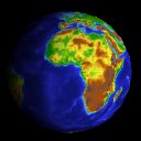
With the texture map applied, the sphere looks like the planet Earth. The lighting creates a bright to dark gradient on the face of the globe.