Bump Mapping
Bump mapping is a special form of specular or diffuse environment mapping that simulates the reflections of finely tessellated objects without requiring extremely high polygon counts. The following image, based on the Bump Earth Sample, demonstrates bump mapping effects.
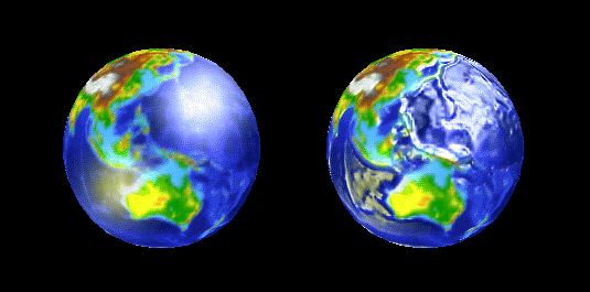
The globe on the left is a sphere textured with an image of the Earth's surface, with a specular environment map applied. The globe on the right is exactly the same, but also has a bump map applied. The polygon count for the second globe is unchanged from that of the first globe.
Bump mapping in Microsoft?Direct3D?can be accurately described as per-pixel texture coordinate perturbation of specular or diffuse environment maps, because you provide information about the contour of the bump map in terms of delta values, which the system applies to the u and v texture coordinates of an environment map in the next texture stage. The delta values are encoded in the pixel format of the bump map surface. For more information, see Bump Map Pixel Formats.
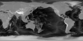
The BumpEarth sample uses a height map to store contour data. When the sample starts, it processes the pixels in the height map to compute the appropriate u and v delta values, based on the relative height of each pixel to the four neighboring pixels.
Direct3D does not natively support height maps; they are merely a convenient format in which to store and visualize contour data. The preceding image is based on the height map used by the BumpEarth sample to produce the bump map it supplies to Direct3D and is included here for descriptive purposes. Your application can store contour information in any format, or even generate a procedural bump map, as the Bump Waves Sample does.
This is the height map image that the BumpEarth sample uses to compute the delta values encoded in the pixel format of the bump map texture.
Bump mapping relies completely on multiple texture blending services, and requires that the device support at least two blending stagesone for the bump map and another for an environment map. A minimum of three texture blending stages are required to apply a base texture map, the most common case. The following figure shows the relationships between the base texture, the bump map, and the environment map in the texture blending cascade.
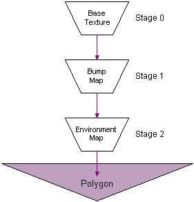
You must prepare the texture stages appropriately to enable bump mapping.
This section provides information about performing bump mapping with Direct3D. The following topics introduce bump mapping, identify and define its key concepts, and provide details about how you can use bump-mapping in your applications.